Opciónes de Descripción:
(1)
Display Resolution and Case Style seleccionar de: 2 para ±1999 counts (3 1/2 digits)
9 para ±9999 counts (4 digits)
(2)
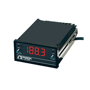
Display & Power Options seleccionar de:0 para LED 120 Vac (49/440 Hz) (BQ20 or BQ90)
1 para LCD 120 Vac (49/440 Hz) (BQ21)
2 para LED 240 Vac (49/440 Hz) (BQ22 or BQ92)
3 para LCD 240 Vac (49/440 Hz) (BQ23)
4 para LED 9-32 Vdc (isolated) (BQ24 or BQ94)
5 para LCD 9-32 Vdc (isolated) (BQ25)
6 para LED 5 Vdc** (BQ26 or BQ96)
7 para LCD 5 Vdc** (BQ27)
8 para LED 24 Vac (BQ28 or BQ98)
9 para LCD 24 Vac (BQ29)
A para LED 26-56 Vdc (isolated) (BQ2A or BQ9A)
B para LCD 26-56 Vdc (isolated) (BQ2B)
(3)
Analog Outputs seleccionar de:0 para 1 mV (DP2) or 0.2mV (DP9) analog output non-isolated. (standard)
1 para 0-5 Vdc non-isolated (BA01)
2 para 0-10 Vdc non-isolated (BA01)
3 para 0-1 mA source or sink non-isolated (BA01)
4 para 4-20 mA source or sink non-isolated (BA01)
5 para 4-20 mA sink (high-compliance) non-isolated. (BA02)
6 para 4-20 mA ISOLATED (BA03)
(4)
Control Outputs seleccionar de:0 para None
1 para Dual-setpoint 10 A relay. (BDT1)
2 para Proportional 4-20 mA control source or sink (BDP1)
3 para Time-proportional solid-state 2 A relay plus proportional 4-20 mA control source or sink. (BDP2)
4 para BCD (isolated latched buffered byte addressable). Includes 50-pin mass-termination connector. (BDD2)
5 para Single-setpoint 10 A relay (BDS1)
(5)
Input Type and Range seleccionar de:E1 para Process Signal Input plus Excitation Output 0.5 V
E2 para Process Signal Input plus Excitation Output 0.5 V
E3 para Process Signal Input plus Excitation Output 0.5 V
E4 para Process Signal Input plus Excitation Output 0.5 V
E5 para Process Signal Input plus Excitation Output 0.5 V
E6 para Process Signal Input plus Excitation Output 10.0 V
E7 para Process Signal Input plus Excitation Output 10.0 V
E8 para Process Signal Input plus Excitation Output 4 to 20 mA
E9 para Process Signal Input plus Excitation Output 4 to 20 mA
E10 para Process Signal Input plus Excitation Output 10 to 50 mA
E11 para Process Signal Input plus Excitation Output 10 to 50 mA
P1 para Process Signal Input 0.5 V
P2 para Process Signal Input 0.5 V
P3 para Process Signal Input 0.5 V
P4 para Process Signal Input 5.0 V
P5 para Process Signal Input 5.0 V
P6 para Process Signal Input 10.0 V
P7 para Process Signal Input 10.0 V
P8 para Process Signal Input 40 to 20 mA
P9 para Process Signal Input 40 to 20 mA
P10 para Process Signal Input 10 to 50 mA
P11 para Process Signal Input 10 to 50 mA
(6)
Display Color seleccionar de:Nada (dejar el campo en blanco) para for Red Display (standard)
-G para Green Display
Nota: Todas las combinaciones pueden no ser válidas, revise la hoja de especificaciones para números de parte válidos